In recent years, with the continuous development of combustion control technology, some fuels with higher calorific value (such as natural gas, heavy oil, etc.) have been gradually applied to the heat treatment process. In the conventional combustion control mode, heating of the heating furnace is generally accomplished by adjusting the flow of fuel and air to sufficiently mix and burn, that is, the flow rate of fuel and air is continuously changed during heating. However, in the case of a high fuel calorific value, the use of a small amount of fuel can meet the requirements of the heat treatment process, so the flow rate of fuel and air is relatively small, and the cross section of the pipeline for transporting fuel is relatively small, if continuous combustion is used. The disc valve that controls and controls the fuel flow is small, and the response capability of the control system cannot meet the flow change requirement, so the error in controlling the temperature is large. In order to solve this problem, some foreign experts have started research and application of the sequential pulse combustion control system since the early 1980s. This control system controls the temperature of the furnace by controlling the combustion timing and combustion time of the burner. Because of its dynamic performance, small temperature fluctuations, and fuel saving, it has received extensive attention and application. Since the beginning of the 1990s, China has introduced this new technology. It has been verified by practical application and has a good effect and has a large promotion value. The following is an example of the composition and control principle of this control system, taking the timing pulse combustion control system of the annealing furnace of Beibei Billiard Iron Pipe Factory as an example.
1. Process introduction
The Beibei Billiards Iron Casting Pipe Factory Annealing Furnace was introduced from Germany IOB in 1994 and has the world's advanced level. The annealing furnace uses a mixed gas as a fuel, and the ductile iron pipe is annealed by direct fire heating. The structure of the furnace is horizontal, with 6 zones, of which 1 zone is the heating zone, the temperature is controlled at 1010 °C; the zone 2 and zone 3 are the heat preservation zone, the temperature is controlled at 970 °C; the zone 4 is the cooling zone; the zone 5 and 6 are In the low temperature zone, the temperature is controlled at 700 °C. The pipe is driven by the conveyor chain in the furnace and enters from Zone 1 at a certain speed and outputs from Zone 6. According to the design requirements, the gas value of the gas used in the Beibei Billiard Iron Pipe Factory is 9200kJ/m3 and the pressure is 8000Pa. Since the tubes are heat-treated in zones 1, 2, and 3, the temperature is still above 500 °C when reaching zone 5, so the heat load in zones 5 and 6 is low, and the flow rate of the gas used is small. There are 4 burners in Zone 5, and the total gas flow rate is about 250m3/h when burning. There are 6 burners in Zone 6, and the total gas flow rate is about 350m3/h when burning. The gas pipeline in Zone 5 has a diameter of 100 mm, and the gas pipeline in Zone 6 has a diameter of 120 mm. In order to meet the process requirements, the 5th and 6th zones use a timing pulse combustion control system. Since the 5th and 6th district control systems are basically the same in design, this paper only introduces the composition and control principle of the sequential pulse combustion control system with 5 zones as an example.
2, control system
2.1 Composition and working principle
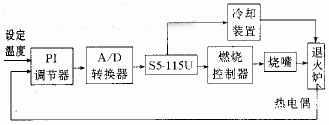
A schematic diagram of the hardware structure of the control system is shown in Figure 1.

Figure 1 Control bear hardware structure diagram
Its working principle is as follows. The temperature of the furnace is set by the PI regulator. The PI regulator samples the set temperature and the actual temperature of the furnace detected by the thermocouple, and calculates the deviation value according to the PI algorithm (ie, the proportional and integral algorithm), and outputs a current signal of 4-20 mA from the magnitude of the deviation value. This current signal is converted to a digital quantity by an A/D converter and sent to the S5-115 UPLC control system. The S5-115U generates a series of timing pulse signals, and controls the different combustion controllers and burners according to the magnitude of the input digital quantity, so that they are ignited or extinguished according to a certain timing, thereby controlling the temperature of the annealing furnace. In Figure 1, the PI regulator uses the KS4290 series of digital regulators from PHILIPS. This regulator is a new type of intelligent regulator produced by PHILIPS in the early 1990s. It can realize two kinds of adjustment methods: positive deviation and negative deviation. When the deviation value calculated by PI algorithm is positive, the regulator works in positive deviation. In the adjustment mode, the output current varies between 12 and 20 mA. When the deviation value calculated by the PI algorithm is negative, the regulator operates in the negative deviation adjustment mode, and the output current changes between 4 and 12 mA. The S5-115U can identify which adjustment mode the regulator operates in based on the amount of digital output from the A/D converter. When the regulator works in the negative deviation adjustment mode, and the temperature of the furnace is higher than the temperature range required by the process (the temperature range of the 5 zone is 690-710 ° C, the temperature range is higher than 710 ° C), the S5-115U is extinguished. Cool all of the burners and turn on the cooling unit to cool the annealing furnace.
2.2 Software Design
In the time-series pulse combustion control system, when the burner is ignited is controlled by the timing pulse signal, and the burning time of the burner is determined by the deviation between the set temperature and the actual temperature of the furnace. Therefore, how to generate the timing pulse signal and how to control the burning time of the burner is a key technical problem that the sequential pulse combustion control system needs to solve. In order to ensure the reliability of the system, the control system uses the S5-115UPLC control system to generate timing pulse signals and control the burning time of the burner.
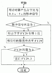
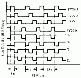
There are 4 burners in Zone 5, which are symmetrically distributed on both sides of the furnace. The S5-115U controls the 4#, 2#, 3#, and 4# burners using the four extended pulse timers T0, T1, T2, and T3, respectively. The timer value of the timer is the value obtained after conversion by the A/D converter. The timer is started by the signal state of the four flag bits of an intermediate flag byte FY29 of S5-115U, that is, when the signal state of the flag bit FY29.3 is 1, the timer T3 is started, and the 4# burner is ignited. When the signal state of the flag FY29.2 is 1, the timer T2 is started to ignite the 3# burner; and so on, when the signal state of the flag FY29.0 is 1, the timer T0 is started, and the ignition is started. mouth. In order to make the signal state of the flag bit set and reset in turn, and then generate the timing pulse signal, FIG. 2 is a block diagram of the program flow.

Figure 2 Flow chart for generating timing pulse signals
In Fig. 2, the pulse signal with a duty ratio of 0.1 s: 5 s means that the time value when the pulse signal is 1 is 0.1 s, and the time value when the pulse signal is 0 is 5 s. When the pulse 1 arrives, the program after the first judgment Y is executed, FY29.3 is set to 1, and FY29.2, FY29.1, and FY29.0 are 0. After the first pulse has elapsed, the program after the first judgment N is executed, and the state of each flag bit is maintained for 5 s. When the second pulse arrives, the bit with signal state 1 will move from FY29.3 to FY29.2, and FY29.3 will be supplemented by 0. At the same time, since the second judgment N is executed, FY29.3 will no longer be set. FY29.1, FY29.0 is still 0. After the second pulse has elapsed, this state will remain for 5s.... When the 5th pulse arrives, two programs for judging Y will be executed, and FY29.3 will be reset to start the next cycle. The various flag bits generated by the program flow chart and the signal states of the respective timers are as shown in FIG.

Next page
Large capacity: This automatic hand sanitizer dispenser has a large capacity of 1000 ml,suitable for use of various disinfectant liquids, liquids and hand sanitizers. for daily use and professional use, perfect for home, hotels, hospitals or other public places. Automatic sensor operated: the touchless hand disinfection machine is designed to nebulize hand sanitizer or alcohol, and provide automatic dosage of spray, which enables a quick and easy hand disinfection and eliminates cross contamination, achieving optimal hand hygiene.
Wall-mounted or Stand Style: Wall mounted soap dispenser that works well in keeping the counter surface clutter free. Battery Operated and Rechargeable:This alcohol hand sanitizer soap dispenser is operated with batteries.This disinfectant hand sanitizer also can be rechargeable with an adapter.(Not equipped with 6V 1A DC Adapter and 4pcs NO2 batteries (C battery))
Convenient and Hygienic: Just put your hand under the sensor to start the soap dispenser, you can effectively avoid cross infection without touching the soap dispenser. Suitable for public places such as offices, hotels, hospitals, medical institutions, schools, etc.
soap dispenser,K9 pro dispenser,automatic soap dispenser,sanitizer dispenser,hand sanitizer dispenser
Shenzhen Lanejoy Technology Co.,LTD , https://www.szlanejoy.com