When an off-road vehicle stops on a well-prepared slope of a road surface, the vehicle landslide (sliding downward) occurs due to insufficient braking torque. According to the parking slope and vehicle parameters calculation, the single rear wheel parking brake torque is required to be no less than 10 034.5 N·m, and the measured maximum wheel parking brake torque of the rear wheel is 5400 N·m, which is far from the requirement.
This paper analyzes the cause of the insufficient braking torque of the rear wheel brake of an off-road vehicle. In addition to the unreasonable selection of the main structural parameters of the brake, which is the main reason for the insufficient braking torque, the insufficient braking force is also the braking torque. One of the main reasons for not reaching the standard. After the improvement measures such as increasing the thrust of the brake chamber output push rod and the length of the brake adjusting arm, reducing the radius of the involute cam base circle, and increasing the strength of the brake shoe, the braking torque can reach the required value.
Brake structure
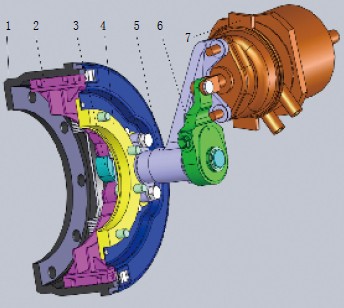
The rear wheel brake of the off-road vehicle is shown in Fig. 1. It is a centering involute cam urging collar hoof drum brake, pneumatic drive, brake chamber is a compound energy storage spring for both service brake and parking brake. Brake chamber. When the brake is braked, the cam mechanism ensures that the displacements of the two hooves are equal. Therefore, the normal reaction forces acting on the two hooves and the resulting braking torque are also equal, and the opening force of the hoof is inversely proportional to its performance factor.

Figure 1 Rear wheel brake structure
1. Brake drum 2. Brake shoe and roller 3. Camshaft 4. Brake bottom plate 5. Camshaft support 6. Brake adjustment arm 7. Brake chamber
Cause Analysis
Physical reexamination
The brake was disassembled, and each component was re-inspected. As a result, it was found that each component satisfies the data requirements, thereby eliminating manufacturing defects.
2. Calculation of braking torque
The braking torque M generated by a single brake is calculated as follows:

Where Q is the thrust of the spring brake chamber output push rod, N;
L——brake adjustment arm length, mm;Η——the transmission efficiency of the cam support;
Rb——the radius of the involute cam base circle, mm;
F'——the coefficient of friction at the point of contact between the cam and the roller;
M——force arm of tangential force (friction), mm;
K1, K2 - the performance factor of the hoof and the hoof;
R - brake drum radius, mm.
The main structural parameters of this brake are: Q=7500N, L=132mm, η=0.6~0.8, and η=0.7 when calculating; rb=13mm, f'=0.15, m=13.62mm, R=190mm, K1=1.01 , K2 = 0.45. It is calculated that the braking torque generated by a single brake is M=5449.58N·m, which is consistent with the measured value (5400 N·m). Therefore, the main reason for determining the insufficient braking torque is that the design is unreasonable and should be improved.
Simulation Giraffe Lights,LED Giraffe Lights,Simulation Garden Giraffe Lights,Outdoor Giraffe Lights of Garden
Sichuan Kangruntengpu Photoelectric Technology Co., Ltd. , https://www.tengpulighting.com