sequence: After a period of hard work, this tutorial finally met with you. In order to help the people who are interested in learning Cimatron quickly master this advanced software, we have written a concise tutorial on the design of the front shell of the mobile phone. Due to the limited time and level, it is not well thought out in some places, and there may be some mistakes and omissions in the text. Please also understand and abide by the readers. In short, the purpose of this tutorial is to let everyone understand the software process and basic operations. In the specific structure, we also need to design the formwork according to the habits of the company. If you find any problems in the tutorial, welcome readers comments and suggestions to us, or send an email to. Since its inception in 1982, CIMATRON's innovative technology and strategic thinking have established its recognized position in the field of CAD/CAM processing. Cimatron E is a new generation of the company's unique integrated technology concept. Its product concept guarantees users a comprehensive product that can work closely together and is easy to learn and use. Using Cimatron E's design and processing solutions, you can increase manufacturing efficiency, and the end result can increase productivity. Supporting practice document download: please click The first part of the demoulding Prepare first.
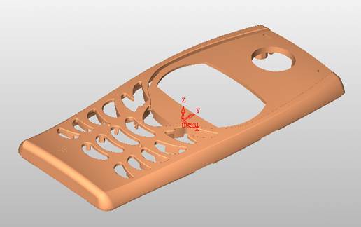
The first step is to import or open a graphical view. In the second step, check the geometry for any problems.
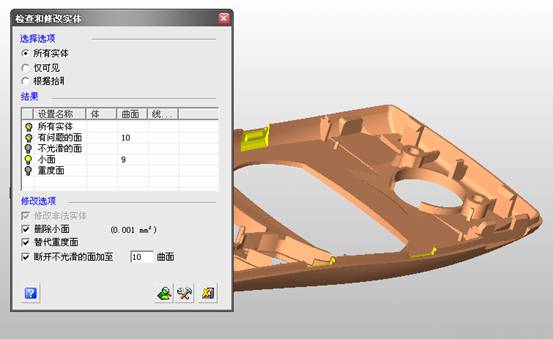
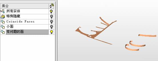
Look at the problematic side, of course you can not see it.
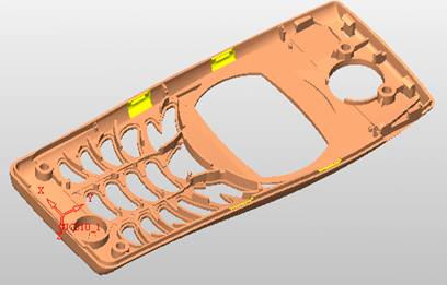
The repair is complete. Looking back, there are a few yellow places that need to be slanted.
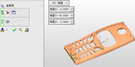
Third, establish a coordinate system
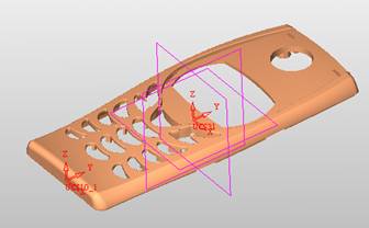
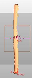
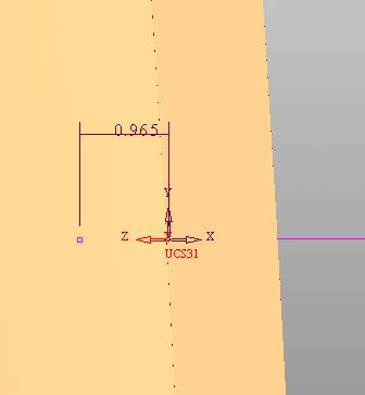
Establish the main plane (three reference planes). Add a sketch point.
Demolished . After the preparation is ready, start the parting.
One of Cimatron's most commendable features is that the courier is disconnected, and you can learn about the power and convenience of the Cimatron surface demodulation through quick disconnect exercises.
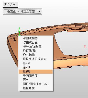
First we need to separate the cavity and the core. At this time we need to choose to split along the Z axis and then select "two directions". Whether the vertical surface is added to the top and bottom depends on personal preference and can be modified later, so generally use "add to bottom".
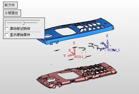
After the software helps you analyze it, the color of each mold part will be changed. In fact, Cimatron E does not make any modification to the surface here, just specify a sliding direction when it is parting. We can set the properties while doing it, which is very intuitive. After mastering it, it will have a multiplier effect. We can drag the slider to see the result of the parting (virtual motion), and then see if there is any wrong face in the direction of automatic designation, manually modify it.
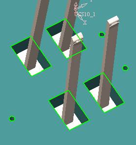
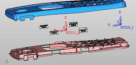
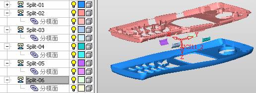
After step by step correction, after the surface of the main part specifies the direction of motion, you may need to make 4 oblique tops.
First select "New Direction" and then confirm. Next, there may be some correct or incorrect faces assigned to this Split. It doesn't matter, the error is canceled, and the correct addition is fine. (For details, please refer to Cimatron E 7.1 Instruction Manual Mold Design Part P15).
Set all the parts, at least you think it is correct.
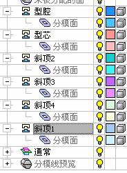
Then modify the name of each Split, so that it is easy to identify, and the output mold part file name will also refer to this Split name.
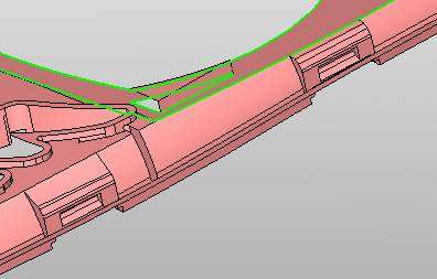
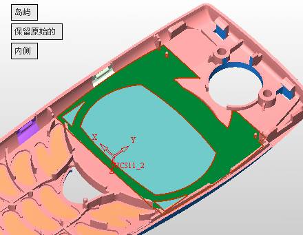
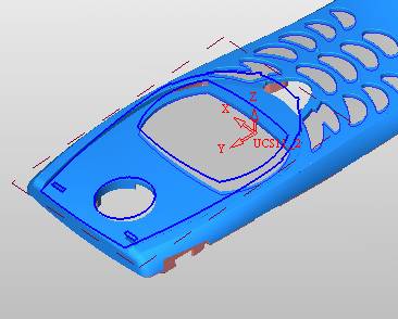
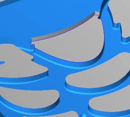
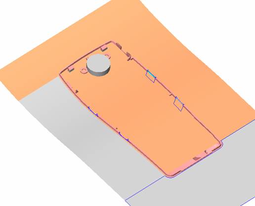
Then make the parting surface, in order to ensure the continuity of the surface and the convenience of processing, we will not use the automatic parting line and the automatic parting surface method here. Among them, we use the "surface - edit - according to the boundary" to make the island part of the surface into a single face shape, while ensuring the same curvature with the front surface. In the actual machining of the mold parts, only the contour changes, there is no sudden change in curvature, which can save time and effort in the processing, and the upper and lower molds are smoothly closed.
When the parting surface is done, you can specify the direction for him. The direction is not just one, because the parting surface is often worn, that is, the cavity has this part, and the core also has In this part, the upper and lower dies must have a common part. This surface is called a parting surface (or an inner parting surface).
Click the model attribute, select the face or quilt to set the attribute, press the middle button, and the button will switch to the second one (as shown below):
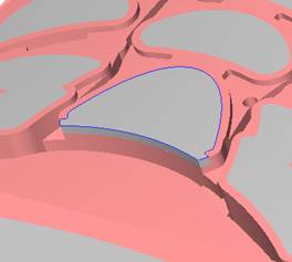
Click on the upper and lower dies to make them appear in deep red. If we confirm at this time, these inner parting surfaces will be attached to the upper and lower dies. After confirming, we can also drag the slider again. At this time, we can clearly see that the color depth of the parting surface and the forming surface will be slightly different. There are a lot of commands that will be used later for editing. According to the sketching and bordering, continue to do the parting surface. For example, in this part, we need to do a better job of wearing the surface. As shown in the figure, if you think there is a better way to come up. The other special inner part profiles are as follows.
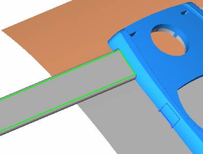
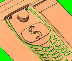
In principle, the parting surface and the forming surface are continuous in curvature, there is no processing dead angle, and there are not many small corners, and the processing is easy (it may also need to use copper, but copper processing is also convenient). The outer parting surface is also required to be manually made. First, the outer contour is commanded by the outer partial line command, and then projected onto the middle plane, and then scanned according to the projected curve, and then the inner part is dug out according to the outer parting line. Figure:
Pillow:
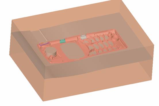
Defining the blank, at this time, the size of the parting surface may be smaller than the predetermined size of the blank. Using the curved surface - editing - the surface can be easily changed by sketching. Note: The parting surface must not be smaller than the blank size, otherwise the cutting will fail in the future.
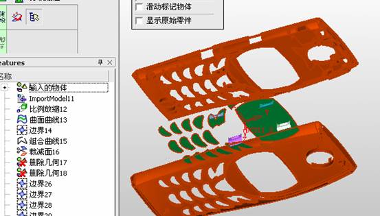
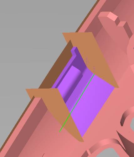
There is also a need to make a slanted top parting surface. In fact, it does not matter whether the parting surface is done before the blank or after the blank, because the real cutting is done after the file is output. When making a split-top parting surface, it is best to hide the blank. Click on the small light bulb to hide it.
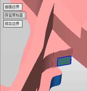
Restore these three faces. Note: When using the boundary command, do not delete the original face. For almost all the production of the parting surface, we should not affect the original forming surface.
Continue and do the cutting.
Draw a line and scan him, plus a 2 degree slope.
The face is not long enough to extend a bit. This can also be used for two-way sweeping when scanning in the previous step.
If you offset this face by 3mm, the thickness of this slanted top is fixed.
Extend the yellow face.
Cut a part as shown.
Copy to the other side.
Extend the extended portion on the other side.
Also cut.
Do some auxiliary lines, auxiliary surfaces and use some surface tools to trim the oblique top related parting surface.
In the same direction, do the other two oblique tops.
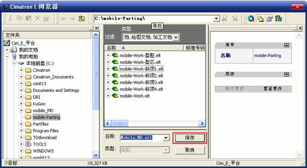
This is the four sloping tops we made. The second part generates the mold part Cimatron E has made even more improvements in file management. After we have removed the mold, we must use the output mold part function to generate the corresponding file. For example, this split model design will generate 6 files.
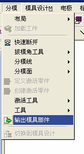
Some people may ask, why not use layers to manage? Isn't it good to enter into 6 SETs? As everyone knows, demolishing the mold is just a very simple pre-processing. There are still many follow-up work, electrodes, engineering drawings, NC, electrode diagrams... If you still like IT, there are seven or eighty layers in a graph, so the speed will be slow. Many, in Cimatron E, the assembly function has been greatly enhanced, so in a picture file, it should only correspond to a single part, this is the best way. If there are multiple parts that you want to put together to check for interference, look at the structure, it is recommended to use the electrode function. The electrode design including Cimatron E is also the operation in the assembly. As long as the assembly is mastered, I don't think it is necessary to forget the level of the past, and the advantage of Set will be reflected after you discard the layer. Gossip less, first execute the mold - output mold parts.
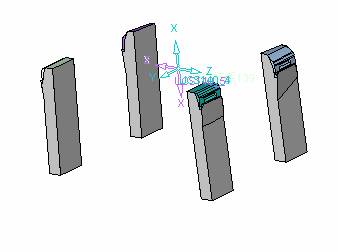
Cimatron will prompt you which documents are output. Then you can see some of the documents as shown in the previous figure, open them separately, and take the cavity as an example to talk about the cutting steps. First, open the document:
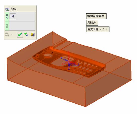
Second, the stitching parting surface
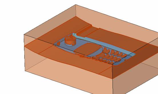
This will stitch the parting surface out.
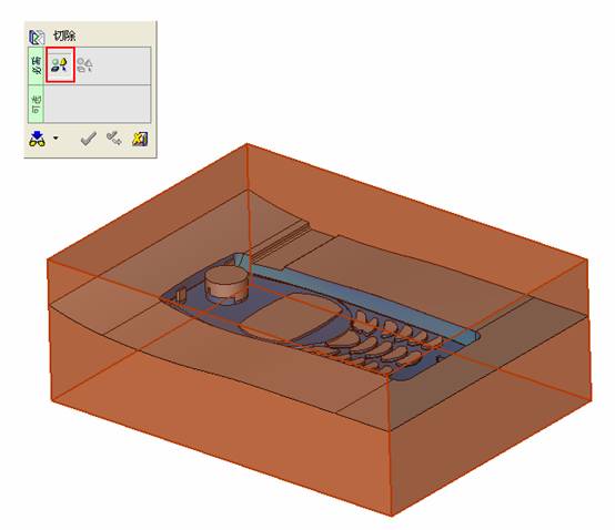
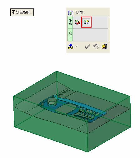
All reddish surfaces are stitched. Third, the removal Select the cut icon. Note that there are two necessary operations for resection, one is the object to be resected, and the other is the object to be resected, which is equivalent to the relationship between cloth and scissors. That is to say, at this time, two elements of cloth and scissors must be selected. Who is Who is the scissors? I think it should be obvious.
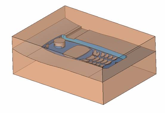
When operating this, take a look at the status bar at the bottom. Now select the object to be cut, you can select the blank, click the middle button to confirm, as shown below:
The embryo will turn green, and this time you choose the parting surface.
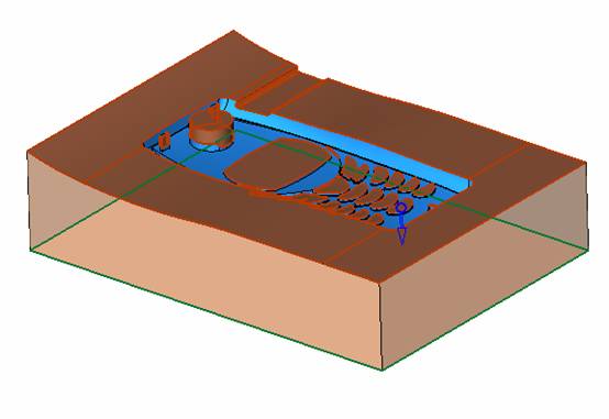
We can see that at this point, the approximate shape has come out and is sure to exit. Now to delete the parting surface, first close all the entity collection, then open the parting surface collection, and delete all the parting surfaces with the delete geometry command. Fourth, stitching Reopen all entities.
Stitching does not mean that this is an entity. Sometimes the model we get or the parting surface may have some small gaps. These small gaps are often not easy to detect, and Cimatron E is dismantling. When the mold is used, the gaps are not considered at all. When cutting, only the gaps existing in the parting surface and the unreasonable parts in the forming surface are considered. That is to say, even if there are some small gaps, it can be smoothly cut off. Hair embryo, but the problem is that some subsequent Boolean operations (such as ejector holes, runners, etc.) may not work, so we must check for gaps.
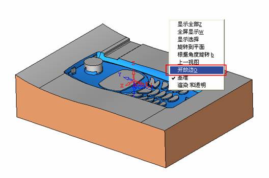
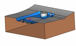
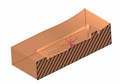
Click the right mouse button and select the open edge . At this time, the dark blue lines will be used to display the open edges. If you don't see it clearly, you can use the section function first to see if there is a hatch. This is also an easy way to check if it is a closed entity.
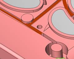
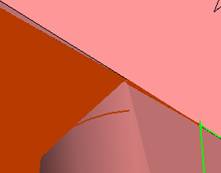
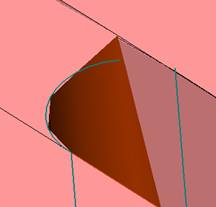
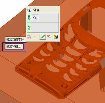
If you can make a closed entity, you're done. If there is an open side, check the problem and do the corresponding modification. In particular, some graphics need to be made into inserts, and the parts must be made into a closed entity, so that some Boolean operations such as physical disconnection can be used. The other figures can be used in the same way. Sometimes, the surface will be deformed:
At this time we can choose to repair and suture when we are sewing.
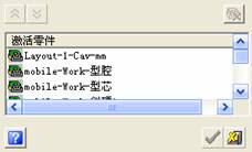
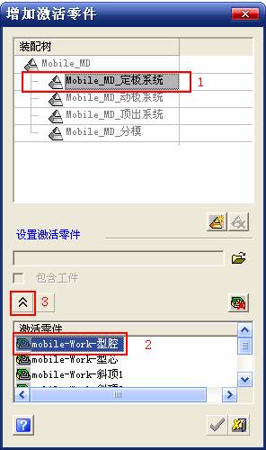
The graphics that come out of this are perfect. If you find other problems, you can continue to use other methods to fix them. The third part of the mold frame structure design Create a mold assembly drawing file. Load the main parts of the mold In fact, the formwork is waiting for the parting, but this step has already been done in the front, and we can load it by adding active parts.
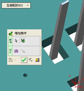
Next, assign the corresponding parts to the corresponding assembly.
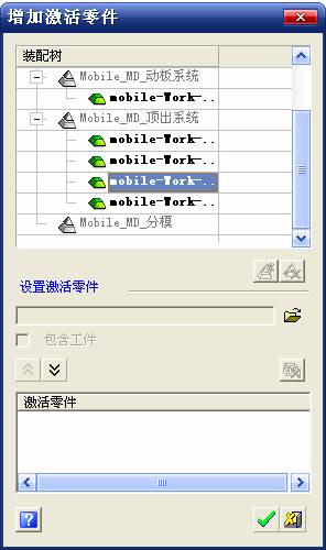
Once set, it will look like the one on the right. Next select the coordinate system and confirm the exit.
Once loaded, the model is laid out according to the established coordinate system.
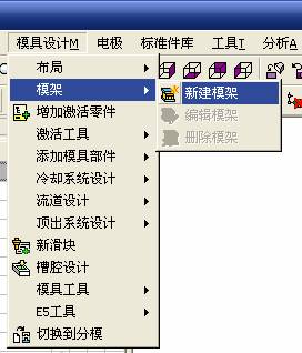
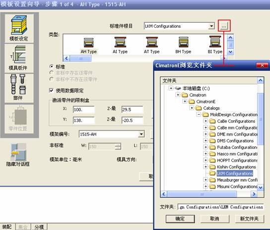
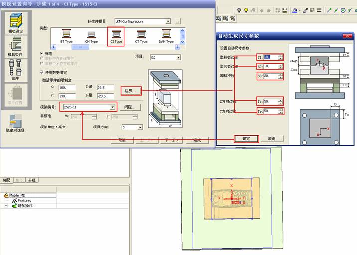
After the core is arranged, you can then select the standard mold base. This is the LKM 2525CI type that we choose. It is not used. It can be selected by a certain offset value.
The following picture, a detailed description of a model of the mold frame generation process, manual selection is ok.
There is a "Mold Direction" option that can be determined according to your needs.
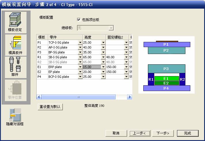
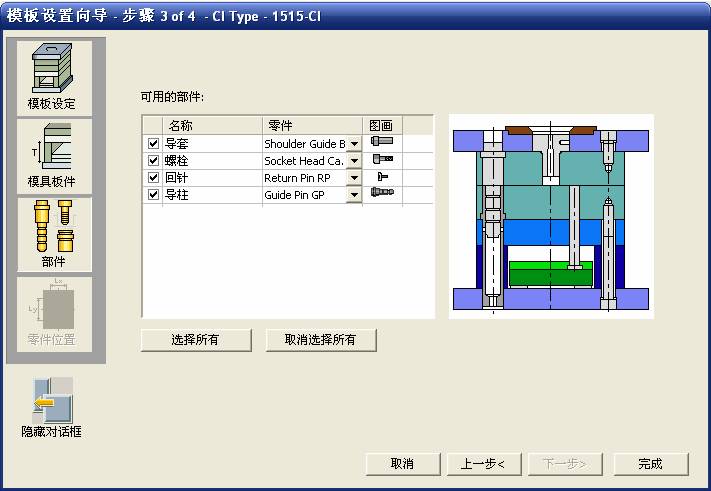
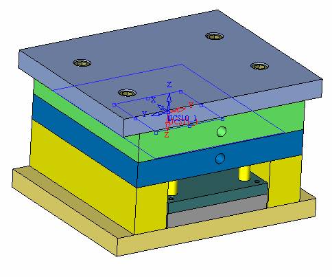
This is the formwork included in the Cimatron E7, which is a typical seven-plate structure. Next, we need to design the relevant mold parts, including the ejector mechanism, slider mechanism, runner design, cooling water design, pocket design and so on. In this case, because the slider is not involved, it will not be described. Here we mainly design the three parts of the flow path, ejection, and cooling. Other related institutions and related functions will be introduced in the future. Introduction.
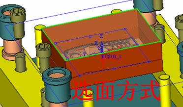
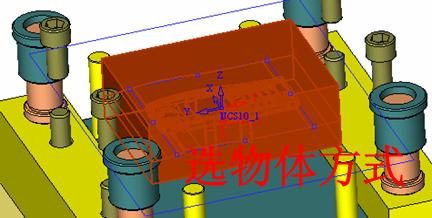
Trenching. The trenching is to use the four (eight) peripheral curved surfaces of the core cavity to dig up the corresponding solids to form a pocket, also known as a mold frame. Click on the grooving command and the cursor will change to
Click on the four surrounding faces on the cavity and core, respectively, a total of eight, the top and bottom are not selected, in the calculation, will automatically close these open boundaries, of course, you can also use another The way is to change the way of filtering the surface into a filter body, and then select the cavity and the core separately.
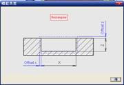
After selecting the required objects, click the middle button, which will have a longer calculation time, but the result is the same. The specific use of the two methods can be found in the help documentation. Then see the corresponding option, if we click on the "Rectangle" option, you can see several corresponding Offset values. If you click the offset again, then there will be three XYZ items, which can be specified separately. For example, when we separately process the mold frame and the core, we need to leave a certain clearance, otherwise it is too tight to be placed, and it will be difficult to remove it later, too loose and may move. As for the specific value given here, it should be set according to the actual needs. Here we only set it to 0.01 on one side, but the Z value is not given. The sharp corners can be changed to rounded or beveled corners, and the corresponding fillet angle value can be set. Note that all templates will be removed as much as possible when grooving.
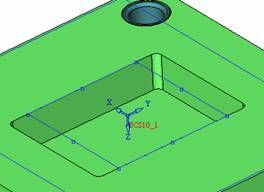
This produces a pocket with rounded corners. Note that this is just a form, the original cavity and core will not change shape, ie no rounding. If your core is rounded, you should make the fillet when you build the blank. As for some related operations, we have to do it several times and it should be understood. Second, the flow channel
Then reuse Next, you need to build a flow path based on the sketch you have drawn.
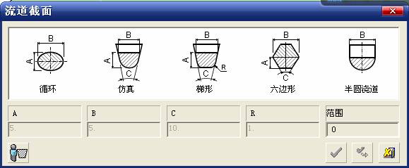
This is a variety of runner shapes supported by Cimatron, which can be selected as needed and then set the corresponding parameters. In this example, a trapezoidal flow path is used, A=3, B=3, C=10, and R=0.8.
At this time, we see that the reverse flow path shape is made. Clicking on the switching direction and the straight port in the option will become the following shape:
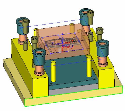
If you feel that the shape is not very good, you can continue to modify the parameters to get the right shape. The model is adjusted to such a display state, all the mold parts are hidden, only the cavity parts and the activated flow path parts are displayed, and the cavity parts are displayed in a translucent manner, so that it can be clearly seen, and then Note the entrance.
The other side is also handled in the same way. Note that when doing these two parts, it is best to use a new entity instead of adding an extension. Do the column, then fuse, no longer repeat them here. Then choose the flow path removal tool
There is a place to add now, that is, a cylindrical insert surface in the upper left part of the flow channel, can be made a little shorter, so that there will be some avoidance on the side of the core, so as to avoid the occurrence of the blockage due to the incomplete processing. phenomenon. When it comes to inserting this structure, you can also change it into a bumper way to extend the life of the mold. cool down Make cooling water, avoid flow passages, screws and other structures. The flow channel is ready to be seen. Screws need to be screwed between the core and the mold frame. In this case, the screws need to be added first.
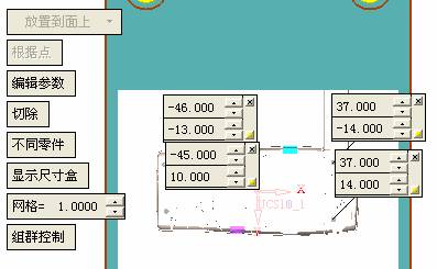
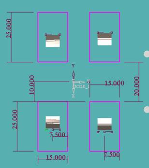
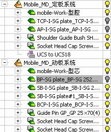
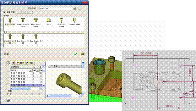
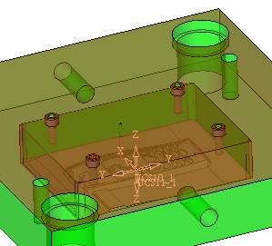
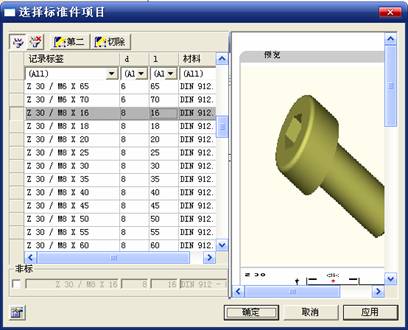
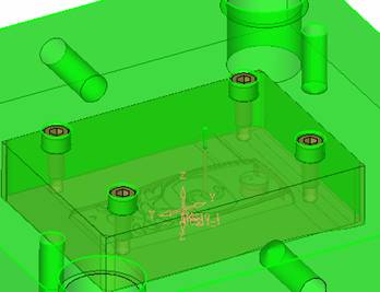
Add four screws to the back of the mold by adding the Screw tool in the mold part. Four standard parts library We use Hasco mm, sub-type Cap Screw, project Cap Screw Z 30, the specific model is Z 30 M 6/16. Next we need to select the placement plane. We select the back of the part AP-I-SG plate_AP-I-SG 2525x40. Then click on the Generate Sketch icon to generate a sketch point as shown (the outer reference circle can be left without drawing). After exiting the sketch, you can see:
If you feel that the screw size parameter is not suitable, you can click "Edit Parameter" to modify it. In this example, you can change it to M8x16.
Under "Edit Parameters" there is a "cut off" option, click on it to switch to "no cut", use the cut option, and the Boolean operation with the template and core generated by the screw, resulting in the corresponding pre-drilled, can Play a related role in the subsequent engineering drawings and processing. The same part means whether the parts are placed in a file four times to create an array relationship or are placed in different components in different parts. If the same part is used, one of the parts will be modified in the future (actually only one part). This will cause the same changes to the other parts, and the use of "different parts" will not produce this relationship. The former is recommended here.
After setting it, click OK to exit. There are several options in the feature wizard. There is no need to change the content here, so there is no way to talk about it. You can try the functions of these functions separately.
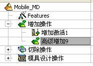
If you think that these screws are too long or the holes are too long, you can right click on the component feature tree to add the last operation. Add 9 to Advanced and then select Edit Features to modify. It will not be modified here, but you can try it. After completing this step, we began to design cold cut water. At this time, when we designed, it was easy to see if interference would occur. Choose cold cutting system design
Click on the sketch Then make a plane and draw the corresponding sketch. In the same way, draw the sketch on the other side.
Click next
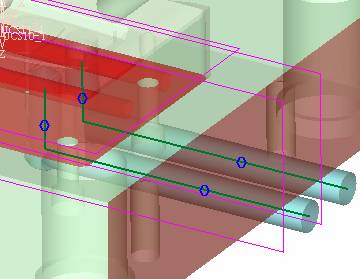
When the extension is set, click on the active object so that this cooling channel is only produced on the core.
Once determined, the waterway can be created. In addition to this, a diversion plug is added to prevent cold cut water from flowing out.
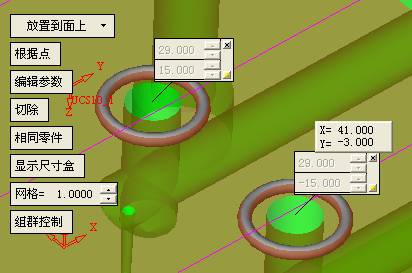
Click When the option appears on the face, click on the corresponding surface, as shown: If you choose the wrong position (should be the center point), you can cancel the diverter by clicking the small fork in the upper right corner of the label. In the same way, three other diversion plugs can be made. Then do the pipeline for water and water.
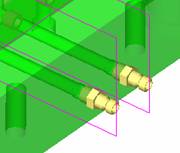
When you are done, add a faucet. It is added in the same way as the flow plug.
This is the picture after the completion. Hide the core, let the frame appear on the screen, then add the O-ring to prevent leaks.
At this point, even if the cooling system is designed, some cooling systems may need to use other parts or structures. We will demonstrate them in future tutorials. Fourth, the ejection mechanism Jack design Of course, hide the unrelated parts. The design of the ejector pin can only show the movable mold core.
We modify d1=2.5; l1=110; l2=50; r=0.3; Then use the sketch point definition, of course, if you feel comfortable, just click directly.
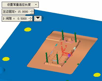
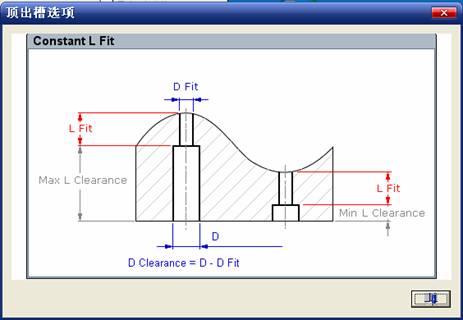
Among them, the cutting option refers to whether the corresponding hole is dug in the thimble fixing plate. Here we also chose different parts options. After the thimble is completed, the ejector can be used to cut the groove and the die and the mold frame are dug out of the hole. Click Then select the blue thimble and the middle button to confirm. Then open the display of the movable mold and the movable mold frame. In the pop-up dialog box, set the constant adaptation length, which means L Fit. You can refer to this figure to make the corresponding settings. Once you're done, you're done.
Next, do the ejector work. Click
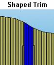
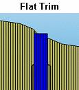
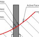
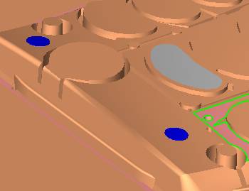
Here we are using the Shaped Trim, and added a 0.1 offset, just to make everyone see more clearly. Inclined top designTurn off the display of all parts except the slanted top, then we have to extend a few slanted tops. Once activated, use Add Extrude. Note that when adding a stretch, the specified direction must be along the line/axis, then select “to reference†to extend it to the fixed plate. Now do it a little easier, first dig holes. Activate ERP plate_ERP 2525 and add delete stretch.
As shown, the penetration will do.
Then, next, do the guiding structure. Activate the ejector structure subassembly to add new component functionality. Select the part, then set the file name "Guide Block 1", then select the UCS in the assembly, OK.
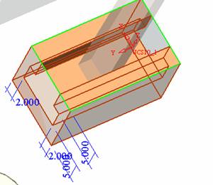
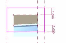
Then we use the function of the new stretch to build a guide block based on the sketch in the figure.
Then, activate the slanted top of the corresponding position and add a T head underneath.
In fact, the structure is added at the bottom of the sloping roof to prevent him from coming out, and the corresponding sliding can be generated when the ejector is ejected. In the same way, add the other three slanted top T heads. Of course, some standard parts can also be used to form a more reasonable and more standardized inclined top structure. Due to the limited number of spokes, we will not introduce them in detail here. We will introduce more corresponding structures in the future. More detailed use of the module. |
Dish Rack,dish drying rack,kitchen dish rack,dish drainer rack,dish rack sink,etc. The materials used are 304 stainless steel, easy to clean, never rust!
China Kichen Rack,Sink Grid,Stainless Mesh Storage Baskets,Kitchen Wire Storage, we offered that you can trust. Welcome to do business with us.
Kichen Rack is made of high quality 304 stainless steel, This kind of material steel luxury, never rust, resist corruption, easily clean, safe, healthy and durable. Prevent rust or chemicals from contaminating food and damaging health
Kitchen Dish Rack,Dish draining Rack,Dish Rack Sink,2 tier Dish Rack
Shenzhen Lanejoy Technology Co.,LTD , https://www.baking-rack.com
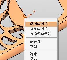
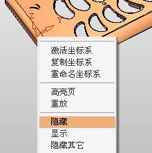




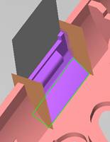
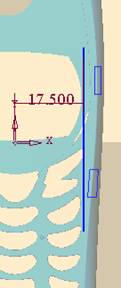
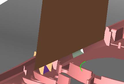
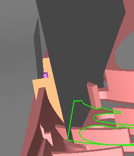
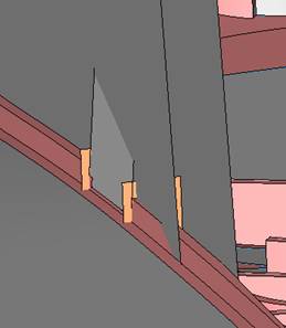
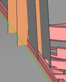
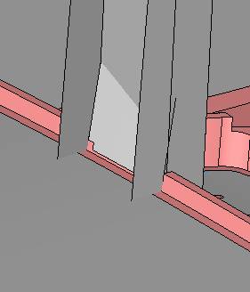
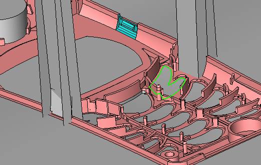
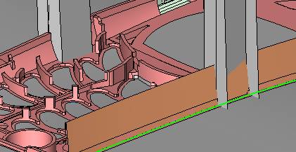
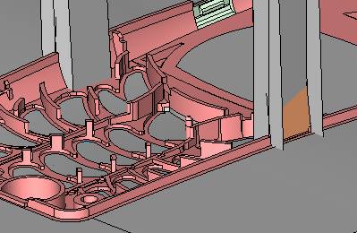

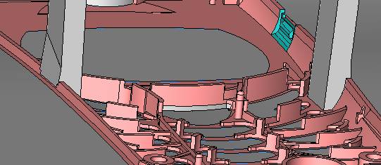
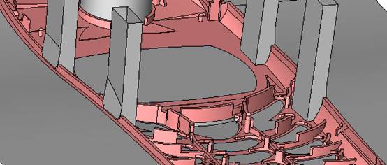

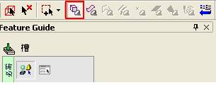
 If you don't see this tool, you should click it first.

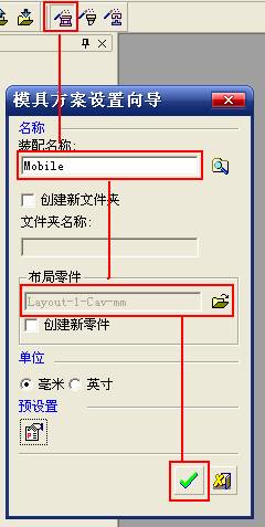
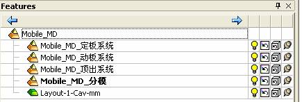
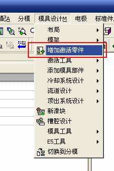
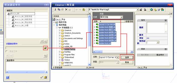




 Click on the parallel plane first,
 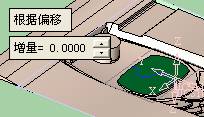 And then use
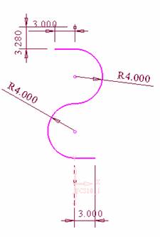
  Tools, create the following sketches,
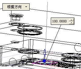
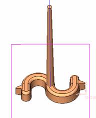
 The tool creates an injection port along the Z-axis. The length can be arbitrary, but it must be longer than the template.
 , cut off the cavity.
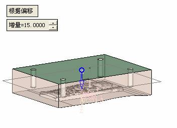
 The following figure produces a corresponding parallel plane. The function of the parallel plane is to make a sketch, and then use the sketch curve to generate a cold cut channel.
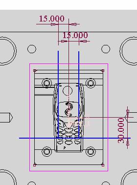
 , select the parallel plane just created, and then draw three straight lines as the centerline of the cold cut channel.
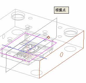
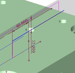
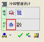 With this option, you can create an extended state. Of course, if there are only two straight water lines, you don't need to use this command. In order to let you know more detailed explanations, the waterway design is now more complicated.
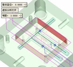
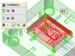
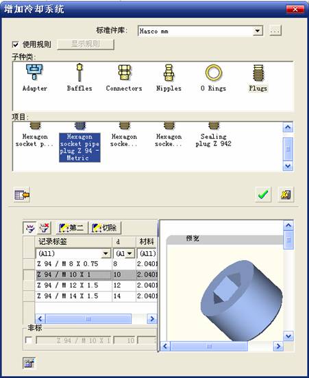
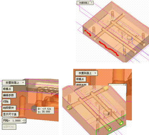
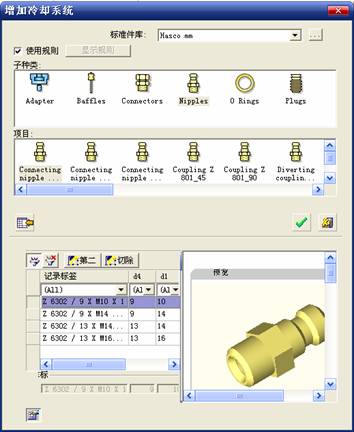
 Then select the Hexagon socket pipe plug Z 94–Metric item under the Plugs sub-category, record the label and select Z 94/M 10 X 1. Click the left mouse button and click OK.
 Click on the add ejector to select the appropriate ejector. In general, the standard ejector is easier to select. Here we have to choose a non-standard ejector to let everyone know how to make simple modifications based on the standard parts. Check the red box on the left to open the second and cut options, then modify as needed.