1 Introduction
In recent years, solar photovoltaic power generation technology has been widely used and developed at home and abroad. The world's solar photovoltaic industry has grown at an average annual rate of over 33%, and the growth rate in 2002 was more than 40%. At present, the installed capacity of photovoltaic systems in the world has exceeded 2.0 GW and will surpass 15 GW by 2010. In the future, solar photovoltaic building integration and photovoltaic grid-connected systems are the final development direction of solar photovoltaic applications. However, the operation of photovoltaic grid-connected power plant systems is generally operated under unattended conditions. Solar photovoltaic power plants are composed of dispersed photovoltaic power generation subsystems, and they are required to monitor and maintain a wide range of geographically dispersed photovoltaic systems. It is very difficult and cumbersome. It requires a lot of manpower and material resources. The local and remote monitoring technologies are used to monitor the photovoltaic power generation system in real time, and these distributed energy systems can be centrally dispatched and managed to achieve the goals of peaking, distribution, measurement, and effective use of the large power grid. The decentralized solar photovoltaic grid-connected systems are linked to form a safe, intelligent, decentralized green energy dispatching management system. Therefore, it is of great significance to study the local and remote monitoring technologies of photovoltaic systems. In particular, the impending energy shortage in China will accelerate the popularization of grid-connected solar photovoltaic power stations in urban and rural areas.
The main content of this paper is to use Ethernet technology to build an embedded Web2Sever with DSP as its core and interconnect it with the Internet to achieve status monitoring, fault detection, data collection, energy scheduling and distribution, and measurement of photovoltaic systems.
2. System implementation principle
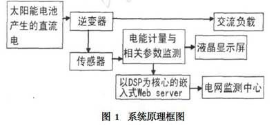
Figure 1 is a system block diagram of a photovoltaic power generation monitoring system. The most important part is the embedded Web2sever with DSP as the core, energy metering and related parameter monitoring, and liquid crystal display. Among them, the electric energy metering part not only needs to measure the amount of electric energy and harmonics converted by the inverter, but also monitors the solar radiation, solar panel temperature, and solar array voltage by collecting information from various sensors. Battery voltage, solar array current, battery current. So it is not a traditional sense of energy measurement, but a fully functional data acquisition system. Therefore, advanced DSP measurement technology is adopted to ensure high accuracy and high stability of the energy meter.

3, system design
3.1 The choice of communication methods
This system adopts the Ethernet communication method, which has the advantages of wide application of Ethernet, low cost, high communication speed, and rich software and hardware resources. Due to these advantages of Ethernet, there are many network communication platforms using Ethernet technology. Advantages: Through the Internet access system, as long as you have a computer, PDA, or mobile phone that can access the Internet, you can automatically monitor the devices in the PV system anytime, anywhere, and optimize management and control of energy. This has great application prospects.
3.2 Design of Network Communication Module Based on ADSP2BF537
The system selects ADSP2BF537 as the main controller. The chip is a high-performance blackfin processor with a clock frequency of up to 600MHZ. It has 132KB full-speed SRAM on the chip and 10 RISC MCU/DSP pipelines. It has a mix of 16/32 bits with the best code density. ISA, powerful and flexible cache is suitable for soft real-time control and industrial standard systems, as well as hard real-time signal processing, and the chip embeds IEEE802.3 compatible 10/100 Ethernet MAC, with buffered oscillator output to separate The PHY is ideal for Ethernet controllers, simplifying circuit design and saving design costs. The physical layer interface chip selects the LAN83C185, which is a low-power and highly-integrated analog interface IC that includes an encoder/decoder, a scrambler/descrambler, a transmitter with shaping and output drivers, and a chip. Intra-Adaptive Equalizer and Baseline Roaming (BLW) Modified Twisted Pair Receiver, Clock and Data Recovery Circuits, and Media Individual Interface (MII) sections integrate DSP with adaptive equalizer to support automatic flow and parallel detection, Operating voltage of 3.3V, fully compatible with IEEE802.2/802/3u standards, full duplex 10BASE2T/100BASE2TX transceiver, support 10Mbps and 100Mbps unshielded twisted pair, complete power management features.
3.3 Design of energy metering module
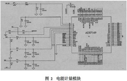
The design uses ADE7169 from Analog Devices, Inc. as the energy metering chip that combines ADI's proven power measurement cores with microprocessors, on-chip flash memory, LCD drivers, real-time clocks, and intelligent battery management circuitry. This not only reduces power consumption but also simplifies the circuit design. After the voltage signal collected by the voltage sensor is filtered, it is sent to the energy metering chip through the 49th pin and the 50th pin, and the current signal is also obtained by the current sensor. After being filtered, the voltage signal is sent to the 52nd pin and the 53rd pin of the electric energy metering chip 7169. Energy calculations for active power, reactive power, and apparent power, as well as measurements of rms voltage and rms current. The circuit diagram of the energy metering module with ADE7169 as its core is shown in Figure 2.

3.4 man-machine interface design
The human interface design includes a liquid crystal display module. LCD module uses TSG128128A series module This series of liquid crystal display module based on SMD technology, the display content is 128x128 dot matrix dot matrix, connection module 22 pin, pin spacing 2.54mm. Typical operating voltage and current; can adjust the contrast, display The effect is clear and the screen stability is good. This module is connected to pins 7-33 of the ADE7169.
4, software design and workflow
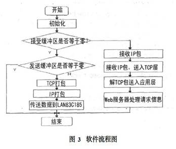
The RJ-45 of this system is the interface between the system and the LAN. Since most LANs use Ethernet, the LAN83C185 is used to handle the Ethernet protocol (IEEE 802.3). The data flow is request information from the LAN, sent to the LAN83C185 through RJ-45, the processed data packets sent to the DSP system's protocol stack, the protocol stack to parse the data packets, get the original request information. The request information is then processed by the DSP system to generate response information. Response information is transmitted to the user's browser over the LAN. The software flow of the entire system is shown in Figure 3.

The software of the embedded Web server in this system is mainly composed of the chip initialization settings, the lwip protocol stack implementation, data acquisition and processing modules. In the program, a user-defined data communication protocol based on the lwip protocol is added. In this way, customized communication can be made between the PC in the customer LAN and the embedded Web server, such as sending data acquisition commands, acquisition parameter initialization commands, and the like. The network layer part adds the Address Resolution Protocol (ARP) to implement the mapping of IP addresses to physical addresses.
The implementation of the protocol stack is mainly divided into the interpretation of the received data packet and the packaging of the sent data packet. Ethernet data is transmitted in frame format. If the frame type field value is 0x0806, it is an ARP packet; if it is 0x0800, it is an IP data packet.
When receiving a frame, it is processed by different software modules according to different frame types. When data frames are sent, they are also packed by different programs according to different frame types. The reception and transmission of frames are based on the physical layer operations on the PHY, including reading the receive buffer and writing the transmit buffer.
Guangzhou Jointair Co., Ltd. , https://www.jointair.cn