4 system function realization
4.1 Implementation of electronic cam
(1) X/Y/Z axis system parameter initialization
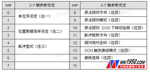
a) Working mode setting: unit, magnification, pulse form, origin return mode, coordinate system, parameter setting are shown in Table 2.
X axis: D1816; Y axis: D1896; Z axis: D1976

Table 2 X/Y/Z axis system initialization parameter setting table
b) Parameter setting: pulse number/moving distance, maximum speed, activation speed, origin return speed, origin return speed, single-speed positioning speed of the motor running one revolution;
X axis: D1818 ~ D1832; Y axis: D1898 ~ D1912; Z axis: D1976 ~ D1992.
(2) Cam working mode setting
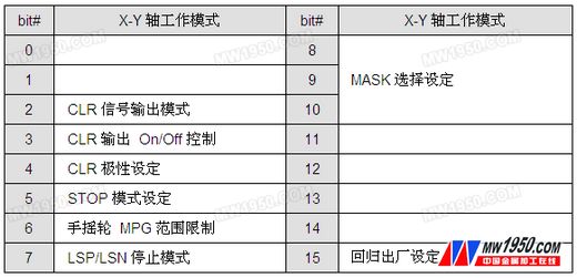
X axis: D1847; Y axis: D1927; Z axis: D2007. Working mode settings are shown in Table 3.

Table 3 X/Y axis working mode setting table
When bit 11 of D1847/D1927/D2007=1, the axis is turned on as the slave axis of the electronic cam. At the same time, this function can also be used to set whether the Y/Z slave axis participates in the electronic cam motion.
(3) Spindle source
There are several ways to obtain the spindle position: one is to use the virtual axis, the calculation is simple and accurate; the second is to obtain the spindle encoder signal from the spindle encoder or servo pulse; the third is to obtain from the measurement encoder. After obtaining the encoder signal, it is converted into the spindle position; the virtual spindle mode adopted in this case, through the unique function of 20PM, can realize multiple electronic cams sharing a virtual spindle from the axis without wiring.
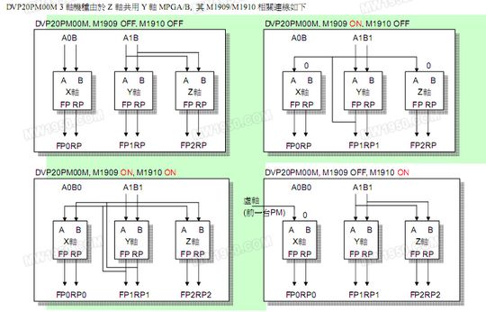
This case uses a virtual spindle method. The virtual axis signal can start M1909 to make the first 20PM Y axis as the virtual spindle. The first and subsequent 20PM X axes execute the electronic cam slave axis. The M1910 can control whether the slave axis follows the virtual spindle. The connection diagram of M1909 and M1910 is shown as in Fig. 2.

Figure 2 Related wiring diagram of M1909 and M1910
Multiple 20PMs share a single virtual spindle processing method, and there is no need to worry about the communication delay and signal attenuation of the virtual spindle after multiple 20PM.
1#20PM M1909=1, M1910=0;
2#20PM M1909=0, M1910=1;
3#20PM M1909=0, M1910=1.
(4) Electronic camming
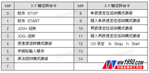
In fact, it is the relationship between the master and slave axes (called the cam table). The cam table has two methods: one is to use the point-to-point relationship of X and Y; the other is to use the functional relationship between the two. The XY axis operation command settings are shown in Table 4.

Table 4 XY axis operation command setting table
The X-axis operation command D1846=H2000, the electronic cam engagement mode is activated. If the Y axis is also a slave axis D1927 does not need to be set separately.
| Previous page | 1 | 2 | 3 | 4 | 5 | Next page |
The Ceiling Fan Light is beautiful in appearance, equipped with durable fan blades and lighting of different colors and styles, and has functions such as lighting, cooling, and decoration.There are much more Led Ceiling Fan styles in our website,such as DC Ceiling Fan ,Iron ceiling fan,Wooden Blades Ceiling Fan With Bulbs,Retractable Ceiling Fan Light,Simple Ceiling Fan Lamp,and best decoration Plywood Led Ceiling Fan.And there are more items are not showing on the website,please feel free to contact us directly for more information.
Big Ceiling Fan,Large Ceiling Fan,Ceiling Fans With Remote Control,Large Industrial LED Ceiling Fan,Industrial Ceiling Fan Light
JIANGMEN ESCLIGHTING TECHNOLOGY LIMITED , https://www.jmesclightingfan.com