The main task of creating a fixture standard piece graphics library is graphics generation. For the similarity of the standard parts, the variable method can be used as the parameter method: for all the geometric features of the original model, given its composition parameters and the range of its parameter values, these variable parameters are called variables, through the input The values ​​of these variables give you the shape and size you need. The standard parts of the combined fixture are designed with the same size, even spacing T-shaped groove, rectangular groove, threaded hole and other structures. Therefore, the following two steps can be used to build the library to simplify the cumbersome and repeated standard part creation process.
The first step is to create a user-defined feature. The UDF establishes UDFs for features such as T-slots and threaded holes on standard parts. Generally, the main UDFs to be created are shown in the attached table according to the series of combined fixtures. Standard components can be created very quickly by simply loading UDF features onto the base geometry as you create each standard.
The second step is to create a cluster table Family Table. Since the components in the same type have similar shapes, using the family table function in Pro/E will do more with less. The Family Table in Pro/E is a collection of essentially similar parts (or components, features), but differs slightly in one or two aspects, such as size or detail. For parts with high reproducibility and similarity (such as screws, wrenches, etc.) or standard parts, it is not necessary to create one part for each specification, but one original sample part (Generic Part) and one cluster table (Family Table) can be used. It can represent an infinite number of parts. Any time you call up the name of any part in the cluster table, you can automatically generate a part of the size shown in the cluster table.
Obviously, family tables greatly increase the use of standardized components. Not only do they allow the actual parts list to be represented in Pro/E, but they also make parts and subassemblies in the assembly easy to interchange (because instances from the same family are automatically interchangeable with each other). However, in the process of creating a cluster table, two problems should be paid attention to the selection of the original model: First, the standard component with the largest size of the same type of standard component is often selected as the original model. Second, when the largest standard part cannot contain all the features of the same type of standard parts, the features not included in the standard part should be added as the original model.
2 Combine fixture design steps with Pro/E
2.1 Creating a workpiece model
Creating a artifact model is done after the standard part library creation work is completed. The first thing to analyze includes: the process diagram, the structural shape characteristics of the workpiece, and the processing requirements of the current process. Then create a 3D solid model of the workpiece to facilitate dynamic simulation assembly.
2.2 Fixture assembly
According to the assembly relationship and constraints between the components, the virtual design assembly is carried out, and the corresponding inspection is carried out, and then the design is analyzed to modify the unreasonable design. Firstly analyze the process diagram, initially determine the positioning, clamping and guiding, tool setting scheme, then directly select the appropriate positioning, clamping, guiding, tool setting components in the standard parts library, and select the appropriate base plate to support these element. Then, the dynamic assembly of the combined fixture can be performed. In the simulation assembly, the assembly sequence should be paid attention to. The positioning component is mounted on the foundation clamp to realize the positioning of the workpiece, and then the clamping component and the guiding cutter component are installed. As shown in Figure 1, the Pro/E design is used to turn a combination of an eccentric outer circle.
| Previous page | 1 | 2 | 3 | Next page |
Oil Casing
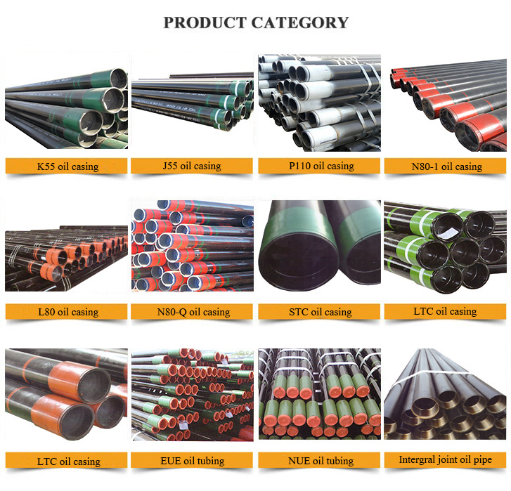
The steel grades of common oilfield API-5CT Casing Pipe include J55,K55,N80-1,N80Q and P110.Casing pipe is mostly used for oil well drilling.In accordance with API-5CT and ISO11960 standard,pipes can be classified as STC(short thread),LTC(long thread) and BTC(buttress thread) accompanied with their couplings.
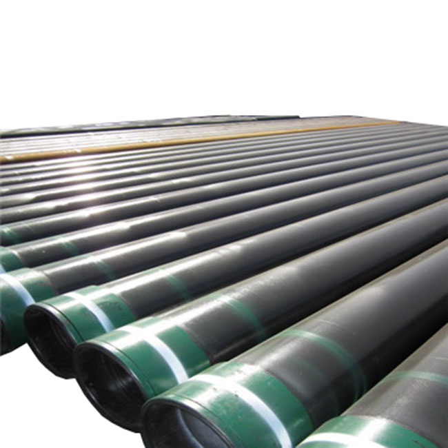
Oilfield Casing Pipes are positioned into well bore and cemented in place to secure both subsurface formations and the wellbore from collapsing,also to enable drilling mud to circulate and extraction to take place.
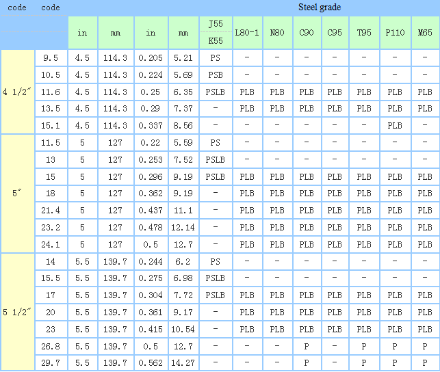
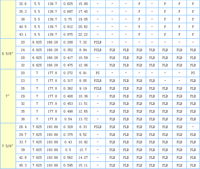
Dimensions And Weight
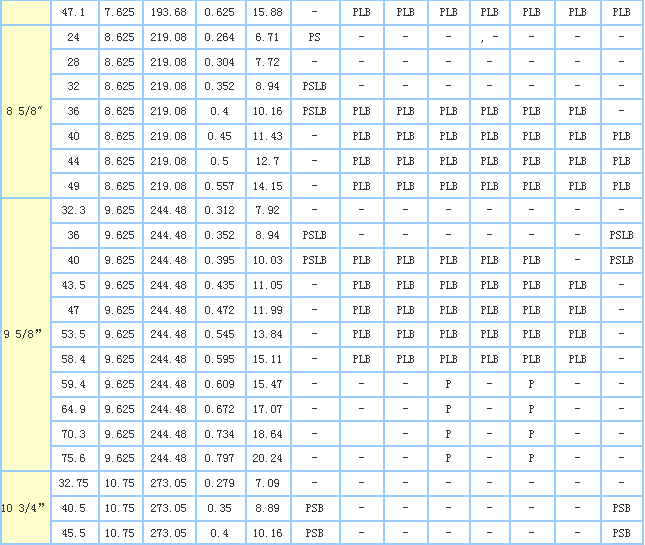
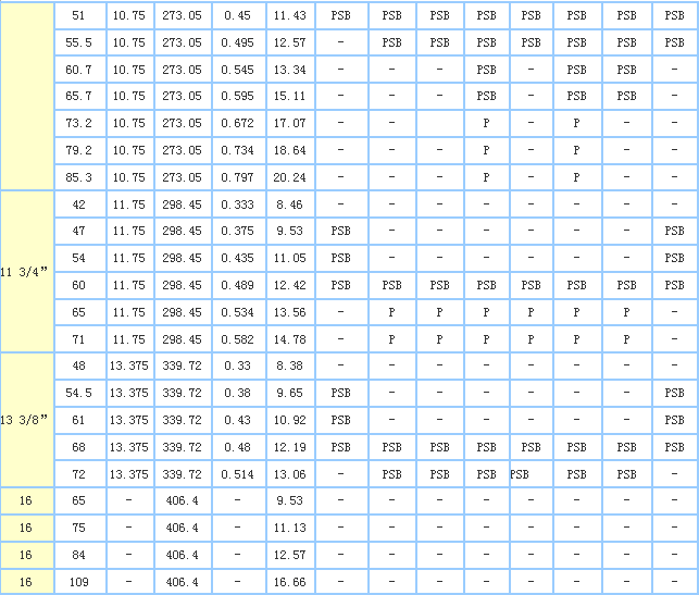

Packaging Details
Plastic caps on both ends, Steel bundle, Woven bag or acc. to customers' request.
Delivery Time
15 days after receiving deposit
If you have any questions, please contact with us directly and welcome you can visit our Factory.
Oil Casing
Casing And Tubing,Oil Casing,N80 Casing,9 5/8 Casing Pipe
HEBEI CHENGYUAN PIPE INDUSTRY GROUP CO.,LTD , http://www.hbcytube.com