An industrial robot is an automated device that mimics human movements and replaces manual handling, handling of workpieces, or operations in accordance with programmed procedures, trajectories, and requirements. Its use is very extensive, and it is of great significance to automate the production process, improve labor productivity, reduce the labor intensity of workers, and ensure the safety of workers, especially for harsh environments such as toxic, dangerous, dusty, deep water and radioactive. Under the conditions of the work, the use of industrial robots has significant advantages. At present, it has been widely used in machining, casting, forging, stamping production lines and certain operations. It has also been developed and applied in the production of heat treatment, welding, painting and assembly.
At present, the common driving methods of the manipulator include hydraulic drive, pneumatic drive and motor drive. Various drive modes have their own characteristics. Hydraulic and pneumatic drive applications are widely used in industrial robots. Some robots use multiple drives at the same time. The way, this depends on the characteristics and requirements of different robots. The hydraulic drive has the following characteristics: the driving force and the driving torque are large, the speed response is good, and the speed adjustment range is large, and is mostly used in a work place requiring a large arm force and a low moving speed.
Overall design
The robot designed in this paper requires handling and loading and unloading workpieces between several mechanical equipment. It has 4 degrees of freedom, which are the rotary motion of the mechanical wrist, the telescopic movement of the robot arm, the rotary motion of the robot arm and the lifting and lowering movement of the robot arm. The coordinate form is cylindrical coordinates, which is controlled by hydraulic drive and used in the production line. A device that automatically transports goods. The structural diagram of the design is shown in Figure 1. The working procedure is: start the robot, send a signal when the workpiece is formed, the arm of the robot is lowered to the predetermined position, the claw is opened, the workpiece is clamped and then raised; then the robot arm is forward Rotating 180°, the mechanical wrist is rotated 90° in the forward direction, the mechanical arm is extended to the predetermined position and then lowered to the designated position, the claw is released, and the workpiece is placed; finally, the mechanical arm is raised to the designated position and rotated 180° in the reverse direction, the mechanical wrist Rotate 90° in the opposite direction, the arm is retracted, returning to the home position and starting the next cycle.
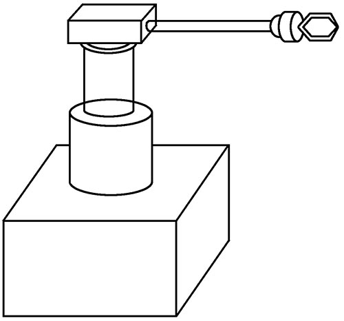
Figure 1 Schematic diagram of the manipulator structure
2. Mechanical system design
For the task requirements of the industrial manipulator, in order to make it have certain operational flexibility and good performance, a cylindrical coordinate system is adopted in the structural design. The entire manipulator system is designed with four degrees of freedom, including up and down movement of the robot arm, horizontal telescopic movement of the robot arm, rotation of the robot arm and rotation of the mechanical wrist. There is no coupling between the four freedoms, which can effectively simplify the calculation and control. In this design, the hydraulic components are mainly used. Therefore, the mechanical arm moves up and down and the mechanical arm horizontally expands and contracts with a double-acting single-piston rod hydraulic cylinder, and the two rotary motions are realized by an inner curved radial motor, as shown in FIG. 2 .
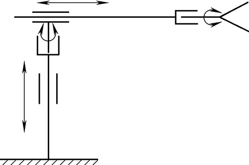
Figure 2 Robot principle
The gripping portion of the robot consists of mechanical fingers, levers, lever supports, wedges, springs, and hydraulic cylinders, as shown in Figure 3. During operation, the pressure oil is introduced from the oil hole into the left chamber of the φ65mm acting hydraulic cylinder, pushing the piston and the wedge forward, and then pushing the lever to rotate around the pin shaft, so that the mechanical finger clamps the workpiece. When the electromagnetic reversing valve that controls the movement of the hand of the manipulator is reversed, the oil in the left chamber of the hydraulic cylinder flows back to the oil tank, and the piston and the wedge are reset by the action of the spring, and the mechanical finger is released by the action of the tension spring.
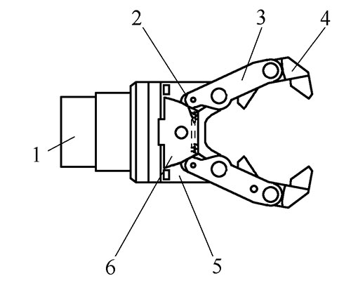
Figure 3 mechanical structure of the claw
1. Hydraulic cylinder 2. Spring 3. Lever 4. Mechanical finger 5. Lever support 6. Wedge
Due to the weight of the hand and wrist of the robot and the weight of the workpiece, when the boom is extended, the piston rod is not enough to withstand their weight. At the same time, the piston rod itself has a high requirement for deformation, so the light bar is used to improve its bearing capacity and reduce the deformation of the piston rod. For the sake of beauty, it can also reduce the force on the piston rod. Install a cover above the boom, which itself can reduce the pollution of the hydraulic cylinder.
3. Control system design
The manipulator designed in this paper is driven by hydraulic system and controlled by PLC. The hydraulic system is shown in Figure 4.
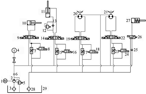
Figure 4 Hydraulic system
1. Motor 2. Pump 3. Suction filter 4. Pressure gauge 5, 12. Relief valve 6, 13, 25. Check valve
7, 15, 17, 23. Speed ​​control valve 8, 16, 18, 24, 26. Electromagnetic reversing valve 9, 14, 19, 22. Electro-hydraulic reversing valve
10, 11, 27. Hydraulic cylinder 20, 21. Motor 28. Return oil filter 29. Fuel tank
The PLC with model FX2N-64MR-001 is used as the core of the control system. It is assumed that the working scene is that the robot moves the workpiece from the ground to the ground, and the control panel is shown in Figure 5. The five positions of the working mode selection switch correspond to five working modes, and the ten buttons in the lower part of the operation panel are manual buttons. In order to ensure that the load power of the PLC can be reliably cut off in an emergency (including a PLC failure), an AC contactor KM is provided. Press the “Load Power†button when the PLC starts running, so that the KM coil is energized and self-locking. The main contact of KM is turned on to provide AC power to the external load. In case of emergency, use the “Emergency Stop†button to disconnect the load power. . The sequence of action of the robot is shown in Figure 6.
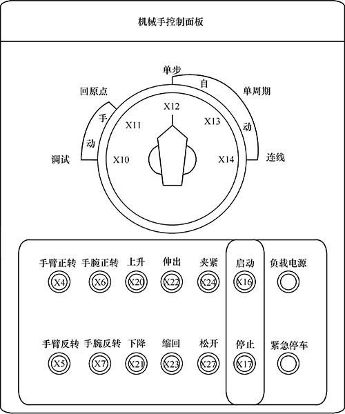
Figure 5 control panel
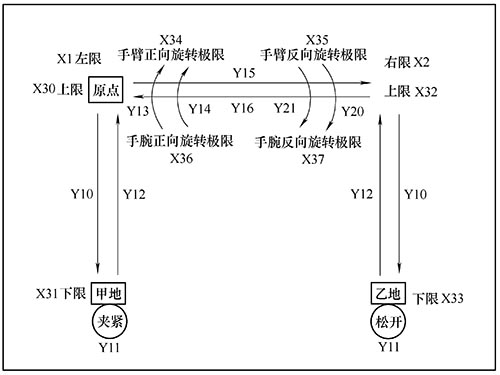
Figure 6 Schematic diagram of the robot movement
4. Conclusion
The robot designed in this paper is mainly used for handling and loading and unloading workpieces between several mechanical devices. It has 4 degrees of freedom, which are the rotary motion of the mechanical wrist, the telescopic movement of the mechanical arm, the rotary motion of the mechanical arm and the lifting and lowering movement of the mechanical arm. The coordinate form is cylindrical coordinates and is controlled by hydraulic drive. The manipulator has a simple structure and a relatively flexible control, and has a large application prospect in an automatic production line.
references:
[1] Shi Zhanqun, Sun Lixin. A PLC-controlled Hydraulic Manipulator[J]. Machine Tool & Hydraulics,1998(6):51-51.
[2] ZHANG Qi, GUO Song-hui, XIE Qing-hua. Hydraulic Manipulator Trajectory Control Based on PD Type Iterative Learning[J]. Journal of Hunan University of Science and Technology(Natural Science Edition), 2005, 20(1): 10-12.
[3] Zhao Xu. Design and control of hydraulic manipulator based on electromechanical and hydraulic integration [D]. Shenyang: School of Mechanical Engineering and Automation, Northeastern University, 2010.
[4] Zhang Yan. Development of pressure-adaptive controller for hydraulic manipulator drive system under deep seawater [D]. Hangzhou: School of Mechanical Engineering, Zhejiang University, 2012.
[5] Jia Qijun.Design and research of radioactive transport vehicle and its application hydraulic manipulator [D]. Changchun: College of Automotive Engineering, Jilin University, 2011.
[6] Wang Zengqi, Xue Lin. Design of automatic watering device for green belt based on hydraulic manipulator[J]. Mechanical Engineering and Automation, 2012(6): 83-84.
Uvc Bulb,T8 Uvc Bulb,T8 Uvc Tube,T8 Uvc Light
Changxing leboom lighting product CO.Ltd. , https://www.leboomuvd.com