This paper mainly focuses on the problem of high deformation over-deformation rate of the front frame of ZL30F loader. By analyzing the specific structure of the front frame, a reasonable welding process is developed and adopted, so that the post-weld deformation of the front frame is obtained. Effective control.
ZL30F wheel loader front frame is an important load-bearing component of the loader. It belongs to the space half-box type symmetrical welded structure. Its main components are left and right wing boxes, bucket cylinder seat, front plate, upper beam, articulated frame, lower Beam and bridge mounting plates, etc. The 3D solid model and its components built by Solidege 3D software are shown in Figure 1.
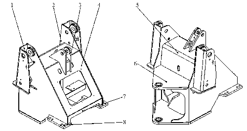
The connection between all parts of the front frame is a continuous fillet weld connection. The right wing box 1 and the left wing box 2 are mainly composed of a wing plate, an outer wing plate, a rib plate, a mounting plate and the like which are connected to the front plate and the upper beam and the hinge frame. Both the wing and the outer wing are 16 mm thick. The main components of the bucket cylinder 3 are 24 mm thick. The front plate 4 has a thickness of 10 mm. The upper cross member 5 is a bent piece and has a plate thickness of 24 mm. The upper and lower hinge plates of the main assembly of the hinge frame 6 have a thickness of 36 mm, and the thickness of the four ribs is 20 mm. The lower beam 7 has a thickness of 12 mm. The bridge mounting plate 8 has a thickness of 30 mm. The material is low-carbon alloy high-strength steel Q345A with good welding performance.
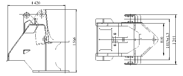
Figure 2 shows the main structural dimensions of the front frame. The three dimensions in the width direction are 810 mm, 1015 mm ± 1.3 mm, and 1 244 mm are structurally critical dimensions.
1 Selection of welding methods
As a high-efficiency, high-quality, low-consumption welding method, CO 2 gas shielded welding is widely used in the welding of structural parts such as the frame of the domestic construction machinery industry. The welding of the front and rear frames of our loader is also protected by CO2 gas. Welding process.
2 ZL30F loader front frame welding process parameters
For the front frame of the ZL30F loader, the thickness of the components is mostly 12 to 24 mm, and only the upper and lower hinge plates and the bridge mounting plate have a thickness of more than 30 mm. Due to the strong arc penetration ability of the particle transition welding, the penetration depth is large and the welding efficiency is high. It is suitable for the welding of 12~50 mm medium and heavy plates. Therefore, the welding of the frame is made by particle transition welding. The welding process parameters are shown in Table 1.
3 Precautions for welding deformation of the front frame
According to statistics, before adopting the process improvement measures introduced in this paper, the maximum deformation of the front frame reaches 4.5-5.5 mm, which is reflected in the shrinkage deformation of the transverse dimensions of the two hinge holes on the upper left and right wing boxes of the front frame. The rate is above 20%, of which 85% of the deformation reaches 4 mm. In order to control this critical dimension (1 015 ± 1.3) mm (see Figure 2), we have taken the following improvements in the welding process:
(1) Point-solid assembly using inverse deformation method
For the prevention of welding deformation of the front frame, since the amount of shrinkage deformation after welding has been predicted, when designing the welding fixture, the distance between the upper gears of the wing boxes on both sides is set to 4 mm (note that the balance is to be with the center of the frame) symmetry). Tests have shown that the size (1 015 ± 1.3) mm can be guaranteed after welding.
In addition, a support rod is designed by adjusting the two-way adjustment nut in the middle of the support rod to the standard size plus half of the free deformation. During the welding, the adjusted support rod is placed in the middle of the two wing boxes. After welding, the nut is loosened and the support rod is removed. The weldment is free to shrink a little and then meets the requirements of the structural standard size. Practice has proved that when using rigid support welding, only half of the free shrinkage of the weld can be reserved.
(2) Adopt reasonable welding process parameters
Welding heat input is a key factor affecting the deformation of the weldment. When the welding method is determined, the heat input can be controlled by adjusting the welding process parameters. Under the premise of ensuring the strength of the weld, the welding parameters of small specifications should be adopted as much as possible. Weldments with symmetric cross-section shapes and symmetrically arranged welds shall be welded symmetrically during welding to ensure that the weld heat input for each weld shall be the same. If the weld distribution is asymmetrical, the welds at the edges of the structure are multi-layer welded, and each layer is small-sized to minimize its effect on component deformation.
For the front frame, because it is a symmetrical structure, the two welds that have the greatest contraction deformation are the fillet welds at the joint between the wing boxes of the two side frames and the frame of the front frame. The joints have no bevels and the height of the weld feet is 10 mm. The slits are symmetrically arranged with respect to the center plane of the front frame. In order to reduce the welding deformation, the welding should be carried out with small gauge parameters. Because the weld bead is large and the length is long, in order to reduce the deformation, two layers and three welds are completed during the welding. Cross welds are used for welding, each length is about 100 mm. The adjusted welding process parameters are shown in Table 2.
(3) Choose a reasonable assembly and welding sequence
In order to reduce the amount of welding deformation of the overall welded structural member, the components are separately welded, and then the overall assembly and the welding of the front frame assembly are performed.
When designing and compiling the welding process of the front frame of the ZL30F, the left and right wing boxes, the bucket cylinder seat, the intermediate beam and the articulated frame are separately used as sub-components, and the respective welding fixtures are designed for each sub-component, and the welding is completed separately, and then The sub-assemblies are assembled into a front frame assembly to perform assembly welding. This plays a very good role in controlling the overall welding deformation. In fact, this assembly welding is highly efficient and suitable for large-volume flow operations.
Symmetrical welds on symmetrical structures are preferably welded simultaneously by multiple welders symmetrically to compensate for deformation in both the forward and reverse directions. If the conditions do not allow, you can only weld one side first and then the other side. At this time, it should be noted that with the same process parameters, the deformation caused by the side of the first weld is always larger than the side of the post weld. Therefore, it is recommended to change the first welding side to multi-layer multi-pass welding, and reduce the welding heat input of each layer (channel), and then use the alternate welding sequence on both sides, so that the deformation caused by each side can be finally offset. When the weld is asymmetrically distributed in the structure, if the weld is located on both sides of the neutral axis of the weldment, the deformation can be controlled by adjusting the order of welding heat input and alternate welding; if the weld is distributed on the side of the neutral axis, only It can be solved by reducing the welding heat input or taking anti-deformation measures.
4 Conclusion
Due to the improved welding process measures, the amount of post-weld deformation of the upper part of the front frame wing box has decreased, from the original 4.5 mm to 2 mm, and the failure rate due to the welding deformation is more than 20%. Reduced to the current 5% to 10%, greatly reducing the post-weld repair rate, meeting the product quality requirements, and improving production efficiency.
Round Concealed Shower Set,Head Rain Shower,Head Rain Shower Set With Brass Arm,Conceal Shower Faucet Set
Kaiping Rainparty Sanitary Ware Technology Co.,Ltd. , https://www.rpshower.com