In order to scientifically carry out innovative design of machine tool products, a new creative machine tool design method has appeared in recent years. According to the tool and the surface information to be processed, the forming motion of the machined surface is analyzed, and the movement function is created and formed. The motion function module combines the various motion function modules according to different assembly relationships to form a general layout plan of the machine tool. This article focuses on how to create a motion function module and assemble the module.
2 Creation of the motion function module
The basic size of the functional module is created
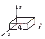
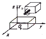
In the motion function structure of the machine tool, the movement is assigned to the tool side and the workpiece side based on the foundation. For example, the motion function structure type W/X.ZY/g p /T["W" means the workpiece, "T" means the tool, "." means the base (foundation) position, and the base position to the "W" means the workpiece side. "X" indicates that the side is assigned a motion in the X coordinate direction, and the tool side is represented from the base position to "T", and "ZY" indicates the motion of the side assigned with the Z coordinate and the Y coordinate direction, respectively, "g p " Indicates that the main motion is the rotary motion of the tool, and "/" is the separator]. The following describes the creation method and steps of the machine structure form by dividing the tool side and the workpiece side. Establish the overall coordinate system of the machine tool and determine the machining space (Fig. 1a). The movement stroke is initially determined by the machining space.
 (a) |  (b) |
| Figure 1 Positional relationship between tool and machining space | |
Determine the structural form of the tool side motion function. The relevant shape and size of the joint and the next level module are determined according to the motion stroke, the nature of the motion unit, and the upper level module.
Determine the structural form of the workpiece side motion function. For example, the position of the workbench can be determined based on the machining space of the workpiece. The length or width of the base can be determined according to the X-direction stroke and the size of the table joint. The height of the base is determined to meet the requirements of the third dimension in the machining space.The workpiece side is coordinated with the size of the tool side. The size of the two needs to be coordinated in consideration of the stroke, retraction and interference.
Data structure description of the motion function moduleThe spatial size and shape of the motion function module can be described in Auto-CADADS using the following data structures and methods:
Struct CParameter {intType:Struct MsizePara{
Ads realCy1D1, Cy1D2, Cy1L://upper and lower top diameters and heights of cylinders or round tables
Ads realCubeX, CubeY, CubeZ: //The length, width and height of the cubeintSideN: //the number of edges of any polygon
Ads realRelX[SideN],RelY[SideN],RelZ[SideN]://length of each side of the polygon}:
}MSize:voidSetMSize(structCParameter*s,intModelNo)://Set module size
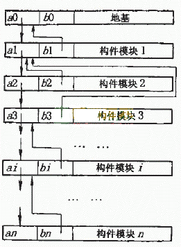
voidGetMSize(structCParameterCs, intModelNo)://Checkout module sizeThe various motion function modules based on the motion function structure should satisfy the assembly relationship in space, that is, the position of any motion function module in the space depends on the position and size of the previous function module, and its position and size. It also affects the starting position of the next function module. Therefore, the above data structure and method are only used to describe the function module. It is not possible to realize the automatic space assembly between the modules, nor can it realize the parameterized driving in the CAD. Add description parameters and methods to the data structure of the function module, as follows:
Struct CParameter {...
Ads pointLocation: //The starting position of the functionAds pointOriention: //The direction vector of the function
... }:
voidGetOriention(struct CParameter*s , int ModelNo)://detects the direction vector of the module
voidSetOriention(struct CParameter*s , int ModelNo)://Set the direction vector of the module
voidSetLocation(struct CParameter*s , int ModelNo)://Set the starting vector of the module
voidGetLocation(struct CParameter*s , int ModelNo)://Check the start vector of the module
 Figure 2 Example of constraint relationship |
 Figure 3 assembly connection relationship of component modules |
Reduced Shank Drill Bits,Stainless Steel Drill Bits,Galvanized Pipe Drill Bits,Reduced Shank Drill Bit Set
Danyang Yongshun Tools Co.,Ltd , https://www.china-drill-bit.com